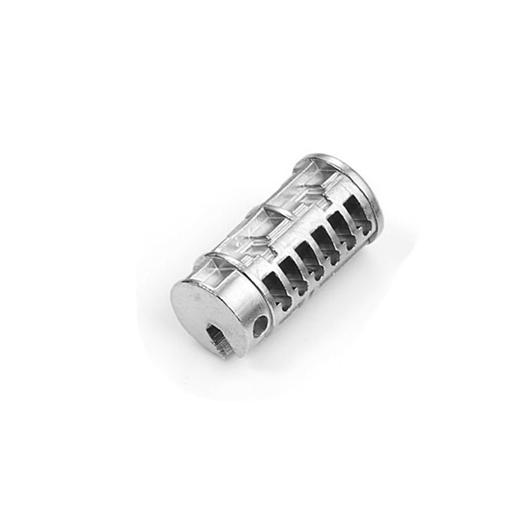
Metal injection molding design means reviewing a part's geometry before tooling to confirm whether it can be molded, debound, sintered and dimensionally controlled as a stable MIM component. For complex precision parts, the design review should not stop at CAD shape complexity. It should check wall thickness balance, section transitions, local mass build-up, holes, slots, flatness-sensitive areas, shrinkage behavior, tooling logic, and which critical features may need post-sinter finishing.
This guide focuses on that engineering decision path: how to judge whether a part is suitable for MIM, where distortion or sampling risk may appear, and what should be clarified before moving into tooling, DFM review or RFQ preparation. The goal is not to repeat every design topic, but to help engineers, buyers and OEM product teams evaluate complex precision geometry before a drawing is released for tooling.
A good MIM design is evaluated across the full process chain, not by CAD shape alone.
A part should not be considered a strong MIM candidate simply because it is small, metallic or visually complex. The better question is whether the geometry can take advantage of near-net-shape manufacturing while remaining stable through molding, debinding, sintering and final dimensional control. Suitability depends less on appearance and more on structural balance, feature logic, and the relationship between function and manufacturability.
Industry references (MIMA's "Designing with MIM") frame MIM selection around four combined factors: shape complexity, material performance, production quantity and component cost. A part is a strong MIM candidate only when geometry, performance target and production logic all support near-net-shape manufacturing from the beginning.
A common mistake in early project evaluation is to assume that a part is a good MIM candidate simply because it looks complex in CAD. That is not enough. A good MIM part is defined by whether the structure remains stable through molding, debinding, sintering and final dimensional verification — not by how many details it contains or how difficult it may be to machine conventionally.
This distinction matters because MIM parts do not move through production as solid, dimensionally final metal components. They begin as molded feedstock-based shapes, then pass through binder removal and sintering, where shrinkage and structural response become central to quality. A part can look manufacturable in CAD and still fail to maintain flatness, hole position or feature consistency after sintering if the internal section logic is poor.
The better way to think about MIM design is to ask a sequence of engineering questions. Is the wall structure balanced enough to shrink predictably? Are critical features located in stable zones? Are local bosses, ribs or transitions creating hidden distortion risk? Is the drawing realistic about which features should remain as-sintered and which may need machining later?
For OEM and industrial product teams, this mindset change matters early. It helps avoid the false assumption that "complex" automatically means "ideal for MIM." In reality, the best MIM designs are usually the ones where complexity is paired with balance, feature discipline and a clear dimensional strategy.
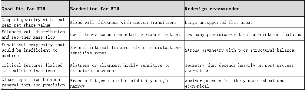
Before tooling, material selection or cost modeling, the first serious design question should be whether the part is structurally suitable for MIM. Not every precision metal component should be forced into the process.
A suitable MIM part usually combines balanced geometry, practical wall distribution and complexity that genuinely benefits from molding. A high-risk design often contains abrupt thick-thin transitions, local heavy zones connected to weaker regions, blind features, narrow slots, or asymmetry that makes shrinkage less predictable. A not-recommended design often asks MIM to stabilize oversized flat areas, hold too many critical features directly as-sintered, or perform in a geometry that suggests another process would be more robust.
This classification changes how the project should be managed. A structurally suitable design may move directly into engineering review. A high-risk design should trigger redesign discussion before cost or schedule assumptions become fixed. A poor-fit design should not be pushed through MIM simply because the part is small. Strong MIM suppliers do not only quote drawings — they also identify whether the geometry is aligned with what the process can deliver consistently.
Not all design risk appears in overall shape. In many MIM projects, the most important issues are created by local geometry decisions that seem acceptable in isolation but become unstable as a system.
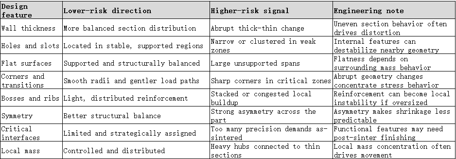
Among all MIM design principles, wall thickness balance and section transition control are usually the most important. Many dimensional and warpage problems do not begin with nominal size. They begin with how mass is distributed through the part. When a thin wall is connected directly to a heavy region, or when one section changes too abruptly into another, shrinkage becomes harder to control. The result may appear later as flatness loss, feature shift, bending or instability around critical functional zones.
This does not mean every wall must be identical. Real parts require variation. The goal is balance that makes structural behavior more predictable. A well-designed MIM part can still contain complex forms and differentiated features, but the transitions between sections should be smooth enough that the part does not create strong local movement during sintering.
Section imbalance is often misdiagnosed as a tooling issue. Teams sometimes try to correct unstable results by adjusting compensation or changing process parameters, when the primary cause is embedded in the design itself. The best design practice is to evaluate parts in cross-section rather than relying only on top-view appearance.
Internal and semi-internal features often create more MIM risk than early CAD review suggests. A hole is not just a hole in MIM. Its final behavior depends on surrounding wall balance, local support, section thickness, and whether the feature is expected to serve as a cosmetic form, a general locating feature, or a true precision interface.
Internal feature design should be evaluated based on function, location and structural impact rather than nominal size alone. A small hole in a well-balanced region may be reasonable as an as-sintered feature. A precision bore near a heavy transition zone may not be reliable enough to remain untouched. A blind hole may weaken a local area more than expected. A narrow slot may introduce sensitivity by reducing local stiffness or increasing uneven shrinkage.
One of the most useful engineering habits here is to separate form features from functional features. If a hole, groove or slot exists mainly to support overall shape or non-critical assembly clearance, it may be acceptable as near-net shape. If that same feature is central to fit, alignment, sealing or performance, the design review should ask whether it really belongs in the as-sintered category — or whether secondary finishing should be reserved for final accuracy.
Many unstable MIM parts do not fail because of one obvious major geometry error. They fail because a series of local feature decisions create hidden imbalance. Sharp corners, stacked bosses, aggressive rib patterns and concentrated local mass can all disrupt shrinkage behavior even when the overall part still appears reasonable.
The better design approach is not to avoid all local features, but to make them work with the structural logic of the part. Radii can improve section continuity. Bosses can remain functional without becoming oversized. Ribs can strengthen a structure if they support balance instead of creating congestion. In many cases, stability improves not by reducing design intent, but by distributing that intent more intelligently across the part.
This is an area where experience matters. Local feature design can look acceptable one decision at a time, yet still accumulate into a geometry that is difficult to stabilize. Reviewing these details as a system rather than as isolated CAD features is often the difference between a robust part and a correction-heavy development path.
Symmetry is not only an aesthetic preference in MIM design. It is often a strong indicator of whether shrinkage will behave more predictably. When geometry is better balanced, mass is more evenly distributed and support conditions are more consistent, the part generally becomes easier to control. By contrast, asymmetrical structures, large unsupported flat surfaces and uneven reinforcement patterns can create distortion even when the nominal geometry looks straightforward.
Flatness is especially easy to underestimate. Broad flat areas often appear simple in CAD, but they are highly sensitive to the rest of the structure. A flat datum may become unstable not because the flat area itself is poorly drawn, but because neighboring geometry pulls the part unevenly during sintering.
Many teams respond to flatness risk by tightening tolerances rather than improving structure. That usually happens too late. Tolerance does not create stability — structure creates stability. The more effective strategy is to reduce the reasons for movement before the part enters tooling.
A MIM part should not be evaluated only in its final-use orientation. It should also be reviewed in the condition in which it will be supported during sintering. Geometry that appears stable in CAD may respond very differently when resting on limited support, spanning a gap, or carrying uneven mass through the thermal cycle.
Key review points:
Is there a naturally stable support region in the part geometry?
Will any long span or thin arm become more sensitive when supported during sintering?
Does the part rely too heavily on a flat face that may not behave predictably as a support surface?
Would a small structural redesign improve support stability before tooling is released?
MIM design cannot be separated from tooling logic. A part may look structurally reasonable in CAD and still become risky if the required parting line crosses a critical surface, if the gate location produces poor filling balance, or if ejection force must be applied under a fragile area.
Parting line location matters because it can affect cosmetic areas, sealing faces and functionally important geometry. Gate position matters because filling path and feed balance influence molded consistency and later dimensional behavior. Ejection matters because delicate regions that seem acceptable in a static model may become vulnerable when force is applied in the green state.
The practical lesson is simple: tooling should not be treated as a downstream problem to solve after the design is fixed. Good MIM development starts when geometry and tooling strategy are reviewed together. If a design forces a poor split condition, an unfavorable feed path or a weak ejection arrangement, the part may become less robust before any process optimization begins.
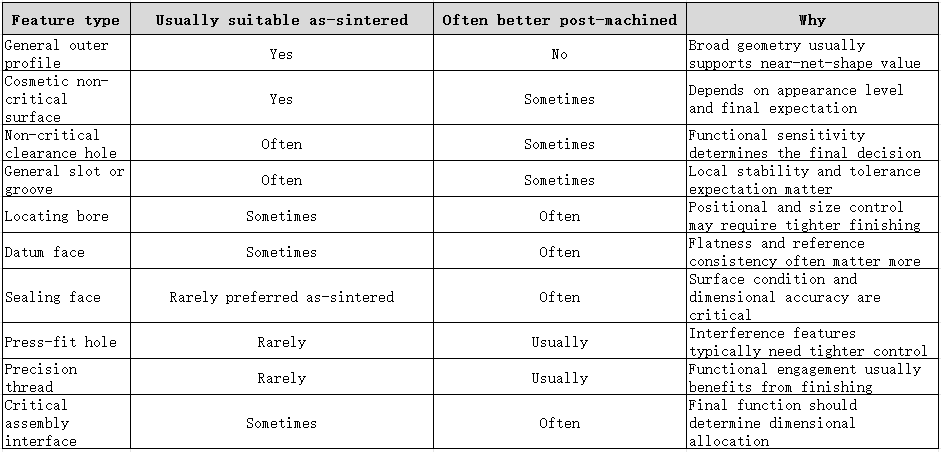
One of the most important decisions in a serious MIM project is not whether a part can be molded, but which features should remain as-sintered and which should be finished later. Good MIM design does not force every feature into the same dimensional expectation. It separates general geometry from critical interfaces and assigns accuracy where it creates the most value.
Many non-critical external forms, general surfaces and broader geometry-defining features can remain as-sintered if the structure is well designed. However, final fit bores, critical datum faces, precision threads and tightly controlled interface features often deserve a different strategy. When these features are central to assembly, alignment, motion, sealing or performance, post-sinter machining may be the more robust and economical choice.
Over-specifying every dimension as though the entire part must perform like a final machined component often reduces robustness and increases cost. A better approach is to protect the near-net-shape value of MIM while reserving selective finishing for the features that truly define function.
Shrinkage is one of the most frequently misunderstood topics in MIM design. It is often simplified as a scaling issue, but real part behavior is more complex. Shrinkage is geometry-dependent. Different regions of the same part can respond differently depending on wall thickness, asymmetry, local support and section transitions.
A balanced structure tends to move more predictably. An unbalanced structure may show directional distortion, feature displacement, flatness change or localized stress behavior that is not solved by compensation alone. The problem is not that the mold was scaled incorrectly — the problem is that the geometry creates unequal movement during the thermal cycle.
This is why shrinkage review must begin as a design review, not as a last-stage tooling correction exercise. Compensation can help refine a stable design, but it rarely rescues an unstable one. If you want predictable MIM shrinkage, start by improving predictability in the geometry itself.
Many repeated MIM development problems come from a small group of familiar design mistakes: abrupt thick-thin jumps, sharp corners in critical zones, heavy hubs connected to thin structures, blind features that weaken local sections, large unsupported flat surfaces, and drawings that expect too many precision features to remain fully as-sintered. None of these conditions is unusual on its own. What makes them costly is how often they are accepted too early and only challenged after tooling and sampling begin.
These mistakes create uncertainty. A structurally unstable part becomes harder to tune, harder to inspect and harder to scale into repeatable production. Even when one issue appears manageable in isolation, several small mistakes combined in one geometry can produce a part that is far less robust than the drawing suggests.
Experienced MIM review often works as pattern recognition. The goal is to identify known instability mechanisms before they become trial-and-error costs — not only to verify whether a CAD model is technically drawable.
Before tooling begins, the design should be reviewed as a production system rather than as a standalone drawing. This stage is where many avoidable MIM problems can still be reduced at low cost.
Part suitability for MIM has been confirmed, not assumed
Wall thickness balance and section transitions have been reviewed
Local mass concentration, ribs, bosses and sharp corners have been checked
Critical features have been clearly separated from general near-net-shape geometry
Features likely to require post-sinter machining have been identified early
Flatness-sensitive zones and shrinkage-sensitive regions have been flagged
Support condition during sintering has been considered in the structural review
Parting line, gate position and ejection influence have been discussed with tooling logic in mind
Sampling validation points have been defined before tooling release
The design has been reviewed for stability, not only for nominal shape completion
The most convincing MIM design lessons often come from before-and-after engineering cases. Unstable results are not always caused by processing error alone — they are frequently rooted in the geometry itself. A part with poor section balance, weak support and heavy local mass concentration may distort after sintering, shift critical features, or lose dimensional consistency in ways that repeated correction cannot fully solve. In these cases, the best improvement usually comes from redesigning the structure rather than endlessly adjusting the tooling.
Case-based learning shows not only that a part failed, but why it failed and what kind of redesign changed the outcome. When a heavy zone is cored, transitions are smoothed, support is improved, or critical features are relocated into more stable areas, the part often becomes more predictable as a system.
For customers and OEM teams, this is where supplier expertise becomes visible. A capable MIM manufacturer does more than report that a part is difficult. It identifies the root cause, explains whether the problem comes from geometry, dimensional expectation or process fit, and helps define the most efficient path forward.
Creative promotion copy: Many engineers release a complex drawing into MIM tooling without checking wall balance, gate position or sintering support — then discover during sampling that the part warps, drifts or fails flatness no matter how the process is tuned. You don't need to learn these lessons through expensive trial-and-error. Send your 2D/3D drawings and functional requirements to Harbermetal before tooling. Our engineering team runs a drawing-based DFM design review, flags shrinkage and distortion risks, separates as-sintered features from features needing post-sinter machining, and gives you concrete design suggestions that reduce cost and protect your launch schedule.
Harbermetal is an ISO-certified full-chain China custom MIM services supplier — a real manufacturer, not a trading intermediary. Our engineering team reviews every incoming drawing as a production system: wall-thickness balance, section transitions, local mass build-up, holes and blind features, gate and parting-line logic, sintering support, and dimensional strategy. We support stainless steel (304L, 316L, 17-4PH, 420, 440C), low-alloy steel, bronze, soft-magnetic alloys, titanium and nickel-base alloys.
We provide pre-tooling DFM feedback, mold development, prototype sampling, vacuum sintering, heat treatment, secondary CNC sizing and diversified surface finishing under one roof. We deliver first-article inspection reports, density/hardness/metallographic test records and full batch-traceability documentation for automotive hardware, power-tool components, lock systems, consumer electronics, wearable devices and non-implant medical auxiliary projects — from prototype validation to high-volume serial production.
Metal injection molding can deliver major value for complex precision parts, but only when the design is aligned with the actual behavior of the process. Good MIM design is not just about making a small metal part with many features. It is about deciding whether the structure is suitable for MIM, balancing sections to reduce shrinkage instability, controlling local feature buildup, protecting critical dimensions with a realistic finishing strategy, and reviewing tooling interaction before sampling starts.
The most important takeaway is simple: the earlier you evaluate a part through MIM design logic, the easier it becomes to control quality, cost and production risk. If a drawing is reviewed only for shape and not for structural stability, problems usually appear later and become harder to correct. If the design is reviewed properly from the beginning, MIM becomes a much more powerful and predictable manufacturing route.
Contact informationEmail: sales@harber-mim.comTel: +86 0769-82389116
What makes a part suitable for Metal Injection Molding?
A suitable MIM part is not defined by complexity alone. It should also have balanced geometry, practical wall distribution, manageable section transitions and a realistic dimensional strategy. The best candidates benefit from near-net-shape production while remaining structurally stable through molding, debinding and sintering.
Why are wall thickness balance and section transitions so important in MIM design?
Wall thickness balance controls how the part behaves during sintering. When thick and thin sections are connected too abruptly, shrinkage becomes less predictable and distortion risk increases. Smooth transitions improve structural stability and reduce the chance of warpage, bending or dimensional drift.
Can all holes, slots and blind features be made as-sintered in MIM?
Not always. Small holes, narrow slots and blind features may be possible, but their stability depends on local structure, surrounding wall thickness and final dimensional expectations. Non-critical features may remain as-sintered, while precision features often need to be reassigned to post-sinter machining.
Is MIM shrinkage just a simple scale factor?
No. Shrinkage in MIM is strongly influenced by geometry. A part with balanced sections usually shrinks more predictably, while asymmetry, local mass concentration and abrupt transitions can create uneven movement. Good shrinkage control starts with better geometry, not only tooling compensation.
Which features should usually be machined after sintering?
Features that directly affect assembly, alignment, sealing or functional accuracy are often better handled after sintering — precision bores, critical datum faces, tight-fit interfaces and some threads. A good MIM dimensional strategy separates general near-net-shape geometry from truly critical final features.
What are the most common MIM design mistakes?
Abrupt thick-thin transitions, large unsupported flat surfaces, sharp corners in critical zones, heavy local mass build-up, unrealistic all-as-sintered tolerance expectations, and feature layouts that ignore tooling logic.
How early should MIM manufacturability be reviewed?
Ideally before tooling begins. Early review identifies whether the part is structurally suitable for MIM, whether key features are placed in stable zones, and whether the dimensional strategy is realistic. The earlier these issues are addressed, the easier it is to reduce cost, save development time and improve production stability.
Ready to evaluate manufacturability for your complex precision MIM part before tooling?
Submit your drawings and functional specifications for a free DFM design review and transparent quotation.
Is MIM suitable for cosmetic visible parts?
MIM can be used for some cosmetic parts, but gate marks, parting lines, pores, polishing allowance, coating route and inspection lighting must be defined before tooling, because polishing, plating or PVD may make near-surface pores more visible.
What are the biggest risks in MIM applications?
Sintering-shrinkage variation, warpage, cracking, porosity, underfill, surface pits after polishing or PVD, heat-treatment distortion, unclear datum strategy and unclear inspection standards.
What should buyers provide for a MIM RFQ?
A 3D model, 2D drawing, material requirement, annual volume, critical dimensions, surface-finish requirement, heat-treatment or coating needs, inspection method, functional requirements and application background.
Ready to determine whether your component is a genuine MIM fit?
Submit your drawings and functional specifications for a free drawing-based MIM suitability review and transparent quotation.
Request A Free Quote

Save money - with manufacturer direct pricing
Save time - with experienced team to get project done
Lead the industry - with the most cutting-edge products
 Send A Message
If you are interested in our products and want to know more details,please leave a message here,we will reply you as soon as we can.
 English