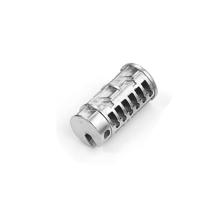
Metal injection molding fits a part when the geometry, material, volume, tolerance strategy, surface finish and inspection requirements all match the MIM process window. A good MIM candidate is usually small, complex, repeatable in production, difficult to machine efficiently, and realistic about post-sinter machining or finishing on critical features.
MIM should not be selected only because a part is complex or belongs to a certain industry. Large parts, long flat parts, prototype-only parts, mirror-cosmetic surfaces and fully datum-critical drawings often need redesign, secondary operations, or another manufacturing route.
This guide walks through how to decide if your component is a genuine MIM fit — using a quick decision tool, a selection scorecard, a part-type matrix, process comparisons, material and tolerance guidance, defect and cost insight, and a practical RFQ checklist — so you screen out bad fits before investing in tooling.
Before comparing suppliers or asking for a price, classify the part into one of three engineering outcomes. This keeps the discussion focused on manufacturability instead of treating MIM as a universal replacement for CNC machining, powder metallurgy, casting or stamping.
The part is small, compact, complex, metal, stable in annual demand, and has realistic tolerance and surface requirements. Only selected features need secondary machining or finishing.
The part may fit MIM, but wall transitions, deep holes, cosmetic areas, datum features, coating requirements or inspection standards need review before tooling.
The part is prototype-only, very large, long and flat, fully datum-critical, mirror-cosmetic without allowance, or too simple for conventional pressing, stamping, casting or CNC.
Engineering rule: Select MIM based on the relationship between geometry, material, production volume, tolerance, shrinkage control, secondary operations and inspection method. Do not select MIM only because the part belongs to a certain industry.
A poor MIM decision usually does not fail at the quotation stage. It fails later — during tooling, injection molding, debinding, sintering, heat treatment, polishing, plating, PVD coating, assembly or mass-production inspection. This is why MIM application selection should be treated as an engineering decision, not only a purchasing comparison.
MIM should be selected only after reviewing the full manufacturing route: metal powder and binder, feedstock stability, mold flow, gate location, debinding risk, sintering shrinkage, density and porosity, dimensional stability, heat treatment, post-sinter machining, polishing, plating, PVD, blasting, passivation, inspection and batch consistency.
Two reference standards anchor this evaluation. ASTM B883 covers ferrous metal injection molded materials (mixing metal powders with binders, injecting, debinding, and sintering with or without subsequent heat treatment). MPIF Standard 35-MIM gives engineers and buyers a common material reference that reduces ambiguity during RFQ, sampling, drawing review, material approval and production acceptance. Both are useful background — but final application selection always depends on your drawing.
Use this scorecard before sending an RFQ. If several items fall into the review or poor-fit column, the part may still be possible, but it needs redesign, secondary operations, tighter validation, or another manufacturing process.
| Selection Factor | Good MIM Signal | Review Needed | Likely Poor Fit |
|---|---|---|---|
| Part size | Small, compact metal part with controlled mass | Medium size with uneven mass or long unsupported areas | Large, heavy, or thick part where debinding and sintering distortion dominate |
| Geometry | Multi-face features, slots, ribs, bosses, undercuts, fine details | Deep blind holes, thin arms, sharp internal corners, thick local bosses | Simple axial pressed shape better suited to conventional PM or machining |
| Volume | Stable medium to high annual demand | Pilot volume with a credible production ramp-up plan | Prototype-only project or frequent design changes |
| Wall thickness | Balanced sections with smooth transitions and reasonable radii | Local thick zones, isolated bosses, asymmetric mass distribution | Abrupt thick-to-thin transitions that cannot be redesigned |
| Tolerance | General molded dimensions plus selected machined features | Several critical-to-function dimensions need review | Every dimension is tight, datum-critical, or inspection-critical |
| Material | Proven MIM stainless steel, low-alloy steel, soft magnetic alloy, titanium or tungsten route | Special material, heat treatment, magnetic, corrosion or wear requirement needs validation | Material is not available or not validated for a MIM route |
| Surface finish | As-sintered, blasted, passivated, polished, plated or PVD with clear criteria | Visible surfaces, cosmetic zones, coating route, pore acceptance need definition | Mirror-cosmetic surface with no polishing allowance or pore acceptance |
| Function | Wear, corrosion, assembly, torque, locking, sliding, magnetic or compact mechanism function can be tested | Function depends on density, hardness, fatigue, coating or surface condition | Safety-critical fatigue or load case without a project-specific validation plan |
| Cost | Tooling can be amortized over stable production volume | Tooling acceptable only if machining and finishing yield are controlled | Low annual demand or excessive secondary operations remove MIM cost advantage |
Application selection should be judged by part type and functional risk, not by industry name alone. A medical jaw, lock cam, wearable hinge and automotive bracket may all be small MIM parts, but each one fails for different reasons if material, geometry, finishing or inspection is selected incorrectly.
| Part Type | Why MIM May Fit | Main Risk | What to Verify Before Tooling |
|---|---|---|---|
| Small gear or drive component | Compact metal geometry, small teeth, repeatable production, reduced machining | Tooth accuracy, wear, heat-treatment distortion, density variation | Material grade, hardness, tooth tolerance, post-sinter sizing or machining, functional test method |
| Lock cam, latch or small mechanism | Complex shape, sliding contact, torque function, high repeatability potential | Wear, hardness, coating adhesion, sliding-surface roughness | Contact area, torque requirement, lubrication, hardness, corrosion protection, cycle testing |
| Wearable hinge or electronics hardware | Small cosmetic metal part with compact geometry and assembly features | Visible pores, polishing marks, gate traces, PVD defects | Cosmetic zone, polishing route, pore acceptance, coating thickness, visual inspection standard |
| Medical instrument jaw or clamp | Small stainless-steel component with complex functional geometry | Functional-edge accuracy, passivation, surface cleanliness, datum control | Critical datum, machined surface, material specification, passivation, functional contact test |
| Automotive small bracket or support | Compact metal part with repeated volume and assembly function | Flatness, wall transition, sintering support, heat-treatment distortion | Wall balance, setter support, gate location, sizing operation, batch inspection plan |
| Sensor or soft-magnetic component | Small magnetic or corrosion-resistant part with controlled shape | Magnetic performance, density, heat-treatment route, test method | Magnetic requirement, material route, density, heat treatment, inspection and validation criteria |
MIM is usually worth considering when the part is small, made from metal, expensive to machine, and needed in repeatable production volume. It becomes more attractive when the part has multiple holes, bosses, slots, internal shapes, undercuts, small mechanical features, or difficult-to-machine material requirements.
Best-fit geometry: Small compact parts with multi-directional features, ribs, holes, bosses, slots, micro-details, or geometry that would require excessive CNC toolpaths.
Best-fit project stage: The design is stable, production demand is credible, and the buyer can provide drawings, CTQ dimensions, material requirements and functional-testing needs.
Best-fit cost logic: Tooling cost can be spread across production volume, and the MIM route reduces machining time, material waste or assembly complexity.
MIM is not the best choice when the process risk is higher than the benefit — often when a part is too large, too flat, too cosmetic, too tolerance-critical, or too low in annual volume. When a shape can be made by conventional pressing and sintering, MIM may also be unnecessarily expensive.
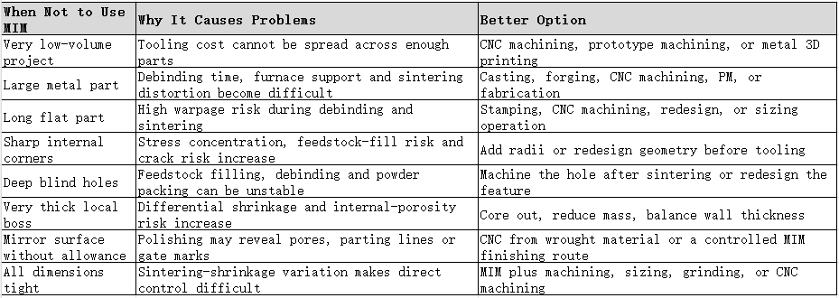
MIM is usually selected when complex small metal parts need repeatable production volumes and reduced machining. This comparison helps separate prototype routes, regular pressed-shape routes and MIM-suitable small complex parts before RFQ.
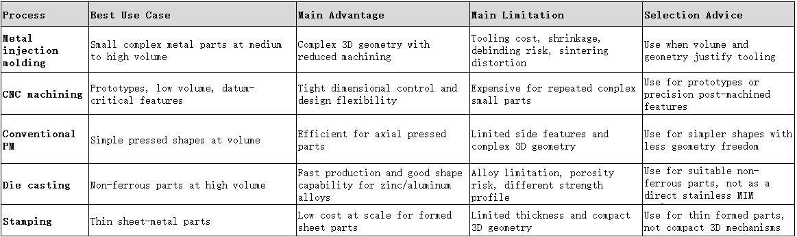
MIM vs CNC is not only a price comparison. CNC is often better for prototypes, low volume, tight datums and frequent design changes. MIM becomes more competitive when geometry is complex, volume is stable, and secondary machining is limited to a few critical features.
MIM vs PM is also not a simple replacement decision. Conventional PM is efficient for simpler pressed shapes, while MIM is better for smaller parts with more complex three-dimensional features, side features and miniature mechanisms.
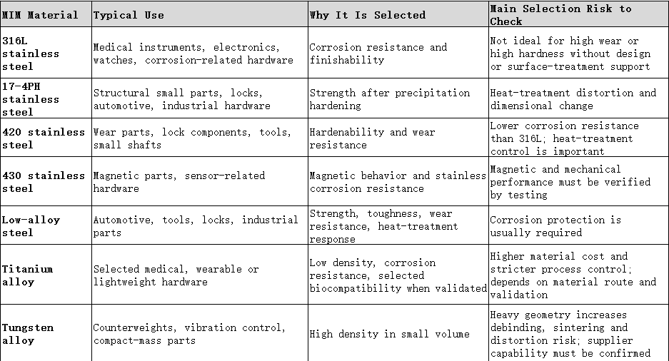
Material selection should start from the actual failure mode, not from industry habit. A wearable hinge, lock cam, medical jaw, automotive bracket and small gear may all be MIM parts, but they do not need the same material. Corrosion resistance, hardness, wear, density, magnetic behavior, heat-treatment response, polishing, plating, PVD and cost should be reviewed together.
MIM tolerances must be discussed by feature type. A supplier may hold general dimensions by mold compensation and process control, but datum-critical dimensions, bearing fits, sealing faces, threads, sliding surfaces and precision holes often need machining, sizing, reaming, grinding or polishing.
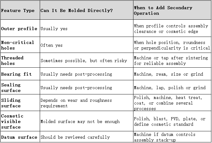
A practical MIM drawing should separate molded dimensions, machined dimensions, sized dimensions, cosmetic surfaces, functional-gauge dimensions and reference dimensions. Because the green part shrinks during sintering, critical datums and precision fits should not be treated like ordinary molded features.
Keep wall thickness balanced. Abrupt transitions increase distortion, cracking and local-density-variation risk. Avoid large isolated bosses, deep thick blocks and sudden changes; core out bosses and add radii where needed.
Avoid sharp internal corners. They raise stress concentration and filling risk, and can become crack-initiation points during debinding or sintering. Add radii wherever function allows.
Review gate location early. Gate position affects flow, weld lines, parting-line placement, density uniformity and cosmetic risk. Review before tooling, not after first samples.
Treat sintering support as part of the design. Parts that look stable in CAD may deform with long unsupported spans, uneven mass or asymmetric geometry. The supplier should explain how the part will be supported in the furnace.
Do not design MIM as CNC without cutting. A CNC design often contains features easy to machine but risky to mold and sinter. Review wall balance, datums, holes, ribs, bosses, deep grooves, sharp edges and finishing routes instead of copying the drawing directly.
MIM surface finish should be selected based on function, not appearance alone. A surface that looks acceptable after sintering may behave differently after polishing, plating or PVD. Pores, parting lines, gate marks, flow marks and polishing waves can become more visible after finishing.
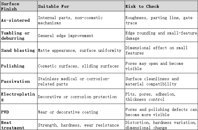
For cosmetic MIM parts, the key question is not simply whether the part can be polished. The better question is what pore level, density, polishing allowance, coating route and cosmetic inspection method are acceptable.
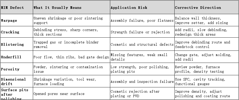
A defect should not be treated only as a visual issue. It often points to a design or process weakness that may affect assembly, surface finish, strength or batch consistency.
MIM cost should be judged by the total manufacturing route, not unit price alone. A low unit price is not useful if the design needs excessive machining, low-yield polishing, repeated coating rework or unstable inspection results.
Major MIM cost drivers include part size and weight, material grade, powder cost, binder and feedstock complexity, number of cavities, tooling complexity, molding cycle time, debinding time, sintering furnace load, yield loss, heat treatment, machining or sizing, polishing, plating, PVD, passivation, blasting, inspection requirements, packaging and handling.
Tooling cost matters because MIM requires a mold. A low-volume project may look attractive technically but fail economically. A high-volume project may look expensive at the tooling stage but become reasonable when machining time is reduced and the cost is spread across production volume.
Many engineers choose MIM simply because a part looks complex, then discover after tooling that deep holes, mirror surfaces or datum-critical features force expensive rework. You don't need to guess whether your component belongs on the MIM route. Send your 2D/3D drawings, annual volume forecast and functional requirements to Harbermetal. Our engineering team runs a drawing-based suitability review — separating molded features from machined, sized and cosmetic features — and tells you honestly whether MIM, CNC, PM, or a MIM-plus-machining hybrid is the most economical path before you invest in any tooling.
Harbermetal is an ISO-certified full-chain China custom MIM services supplier — a real manufacturer, not a trading intermediary. We complete the whole route in-house: feedstock evaluation, custom mold development, metal injection molding, multi-stage debinding, vacuum sintering, heat treatment, secondary CNC sizing and diversified surface finishing (tumbling, passivation, electropolishing, bead blasting, plating and PVD coordination).
Our engineering team reviews every incoming drawing against the MIM process window — geometry risk, wall balance, gate location, sintering support, tolerance strategy, surface-finishing route and material suitability. We support stainless steel (304L, 316L, 17-4PH, 420, 440C), low-alloy steel, bronze, soft-magnetic alloys, titanium and nickel-base alloys. We provide first-article inspection reports, density/hardness/metallographic test records and full batch-traceability documentation for automotive hardware, power-tool components, lock systems, consumer electronics, wearable devices and non-implant medical auxiliary projects, from prototype sampling to high-volume serial production.
Before asking for a MIM quote, provide a 3D model, 2D drawing, material requirement, annual volume estimate, target application, critical dimensions, surface-finish requirement, heat-treatment requirement, coating or plating requirement, cosmetic-surface definition, mechanical-test requirement, inspection method, packaging requirement, prototype schedule and mass-production schedule.
Ask the supplier to confirm MIM feasibility, suggested material, tooling assumptions, expected shrinkage risk, critical dimensions needing machining, surface-treatment route, estimated tooling cost, estimated unit cost by volume, sampling plan, inspection plan and possible failure risks.
A strong RFQ does not simply ask "how much is this part?" It asks whether the part is truly suitable for MIM, which features should be molded, which should be machined, what risks may appear after sintering and finishing, and what evidence will be used to approve production.
Use MIM when the part is small, complex, repeatable, material-compatible and produced in enough volume to justify tooling. Avoid MIM when the part is large, flat, low-volume, highly cosmetic without finishing allowance, or full of tight datum-critical tolerances that require machining anyway.
A good MIM application-selection decision is not based on industry name or part complexity alone. It is based on the relationship between geometry, material, volume, tolerance, surface finish, tooling cost, sintering shrinkage, density, secondary operations and inspection strategy. When these factors are reviewed before tooling, MIM can be a practical manufacturing route. When they are ignored, the project may pass the first quote but fail during sampling, finishing, assembly or mass production.
Contact information
Email: sales@harber-mim.com
Tel: +86 0769-82389116
What is the first rule for selecting MIM?
Confirm whether the part is small, complex, production-volume suitable and material-compatible. MIM should not be selected only because a part has a complex shape.
When should I use MIM instead of CNC machining?
Use MIM instead of CNC when the part is small, complex, produced in medium-to-high volume, and does not require machining on every critical feature. CNC is usually better for prototypes, low volume, tight datums and frequent design changes.
Can I use MIM for a prototype-only metal part?
Usually no. MIM requires tooling, so prototype-only projects are often better tested by CNC machining or metal 3D printing first. MIM becomes suitable when the design is stable and there is a credible production volume.
When should I not use MIM?
Avoid MIM when the part is very large, very flat, very low-volume, too thick in isolated areas, or requires mirror-cosmetic surfaces or ultra-tight datum-critical tolerances without post-processing.
Should I choose MIM based on industry or part geometry?
Choose MIM based on part geometry, material, tolerance, surface finish, production volume and validation requirements. Industry name is only background information.
What materials are commonly used for MIM parts?
Common MIM materials include 316L, 17-4PH, 420 and 430 stainless steel, low-alloy steels, selected titanium alloys and selected tungsten alloys, depending on corrosion resistance, strength, hardness, wear, density, heat treatment and surface-finish requirements.
Do MIM parts need post-sinter machining?
Some can be used as-sintered, but critical holes, bearing fits, sealing surfaces, threads, sliding faces and precision datums often need post-sinter machining, sizing, grinding or polishing.

Save money - with manufacturer direct pricing
Save time - with experienced team to get project done
Lead the industry - with the most cutting-edge products
 Send A Message
If you are interested in our products and want to know more details,please leave a message here,we will reply you as soon as we can.
 English